Settings reference
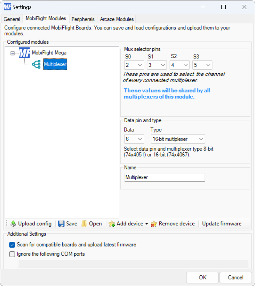
Modules dialog
| Setting | Description |
|---|---|
| S0 | The board pin connected to the S0 pin of the multiplexer. All digital and analog pins are supported. This pin is shared by all multiplexers connected to the board. |
| S1 | The board pin connected to the S1 pin of the multiplexer. All digital and analog pins are supported. This pin is shared by all multiplexers connected to the board. |
| S2 | The board pin connected to the S2 pin of the multiplexer. All digital and analog pins are supported. This pin is shared by all multiplexers connected to the board. |
| S3 | The board pin connected to the S3 pin of the multiplexer. All digital and analog pins are supported. This pin is shared by all multiplexers connected to the board. |
| Data | The board pin connected to the data pin of the multiplexer. All digital and analog pins are supported. This pin must be unique for each multiplexer connected to the board. |
| Type | The type of multiplexer connected, either 8-bit multiplexer or 16-bit multiplexer. |
| Name | The name for the multiplexer. Displayed in the input configuration dialog to identify the multiplexer when mapping the input to a simulator event. |
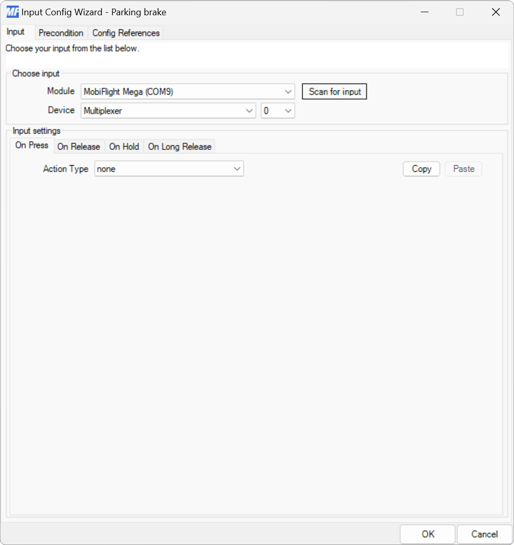
Input configuration
Multiplexers have the same input setting events as buttons and switches.
Use the Device dropdowns to select the multiplexer and specific input on the multiplexer to use.