Troubleshooting
Potentiometers are generally reliable components, but slight variations between the different devices may cause problems when using standard events. This guide will help you troubleshoot common issues with potentiometers.
Handling potentiometer noise
Potentiometers can be affected by electrical noise from the environment. This noise can cause the potentiometer to send random values to the simulator, even when the potentiometer is stationary. This is especially common when the potentiometer is near 7-segment displays.
If you notice that the simulator input is changing value even when the potentiometer is stationary, try these steps:
Reduce the sensitivity
In the Modules dialog, reduce the Sensitivity setting for the potentiometer.
Add capacitors to the devices
Install capacitors on both the 7‑segment display and the potentiometer power inputs. Combined with reduced sensitivity in the Modules dialog, these changes should eliminate the noise.
Move the displays
If the potentiometer is still affected by noise, move the 7-segment displays to a separate board.
Determining the potentiometer range
While most 10kΩ linear potentiometers have a range of 0–1023, some may have a slightly different range. To verify the range of your potentiometer, connect it to your board, then take these steps.
Enable logging
Follow the logging guide to enable info logging.
Move the potentiometer
Move the potentiometer from one end to the other.
Write down the values
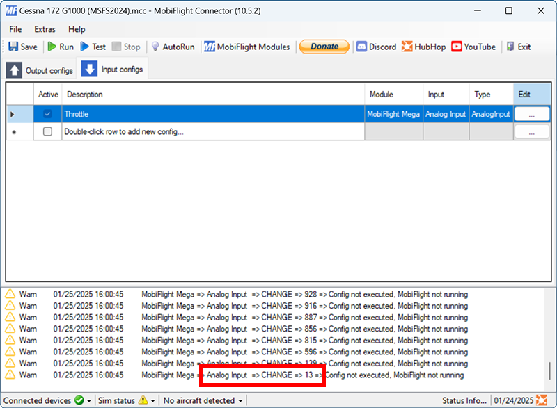
The log will show the values from the potentiometer. Write down the minimum and maximum values from the log.
In the example below, the lowest value produced by the potentiometer is 4. The highest value, not shown, is 1020.
Tip
Don’t forget to disable logging after obtaining the potentiometer values. Logging can slow MobiFlight down during normal use.
Scaling the potentiometer range to the event range
If the range of your potentiometer is different from the standard 0–1023, use the Interpolation modifier to adjust the value before using it with a simulator event.
Add an interpolation modifier to the input config
Click the Modifiers button, then the Add modifier button and select Interpolation for the modifier type.
Set the Device output range preset to Arduino and enter the minimum and maximum values from the log. Set the MSFS2020 event input range to the desired input.
Add the potentiometer values to adjust the range
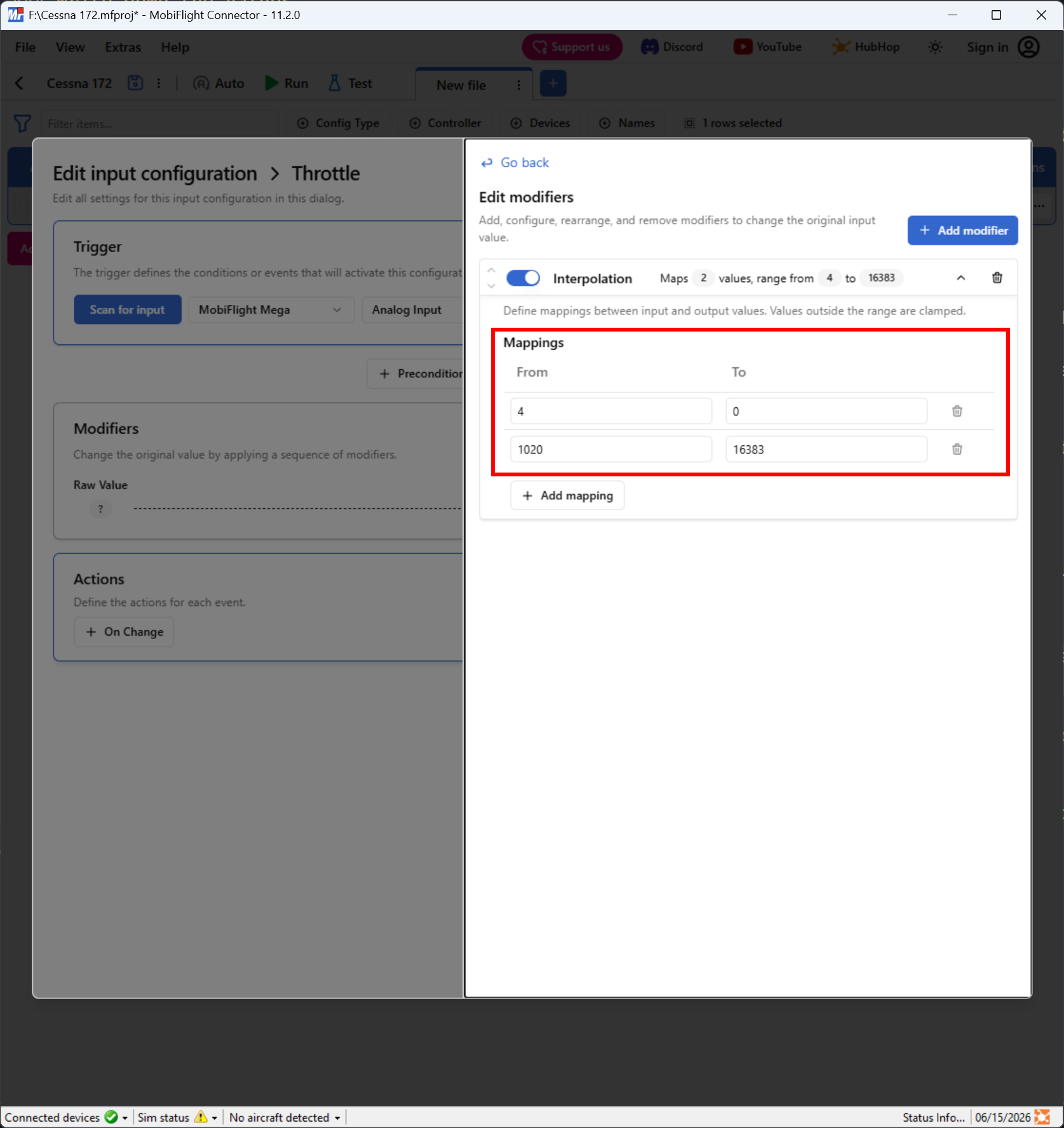
Put the lowest logged potentiometer value in the From field of the first interpolation line. Put the highest logged potentiometer value in the From field of the second interpolation line.
For the To fields, use the lowest and highest values expected by the simulator for the event. Typically, this will be 0 at the low end and 16383 at the high end for axis inputs like throttles.
Tip
The HubHop potentiometer tool has a list of common input events with their minimum and maximum values.
Select the simulator event
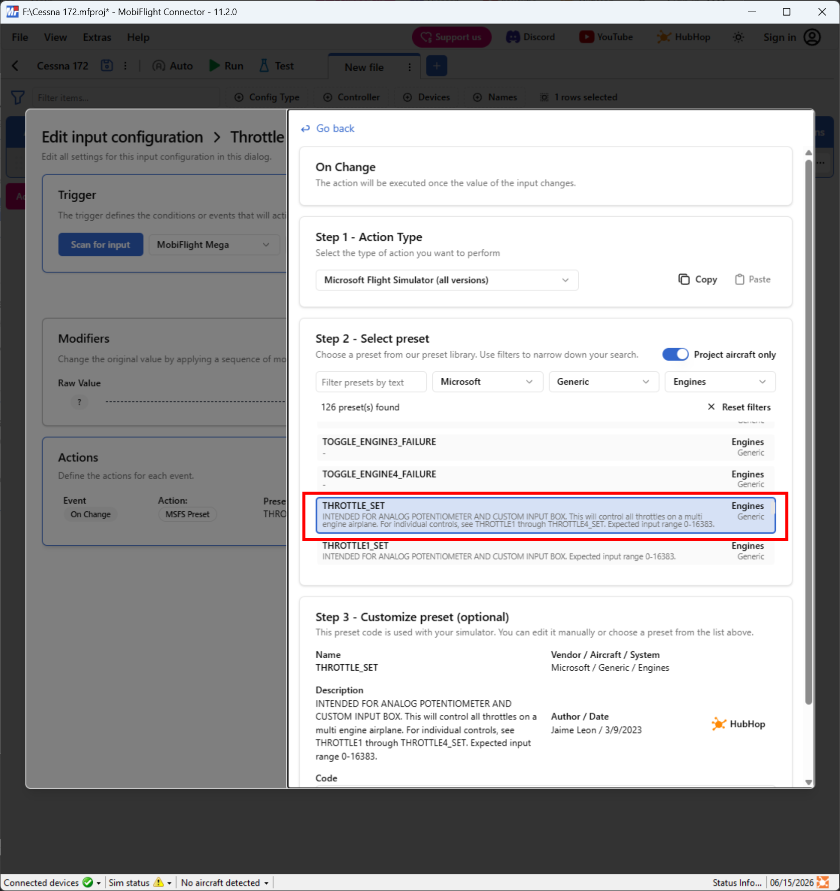
In the input config dialog, use the On Change button to specify the simulator event. For example, to set the throttle position on a Cessna 172 in Microsoft Flight Simulator, filter by Microsoft / Generic / Engines and select the THROTTLE_SET event.
Modify the event code
Most HubHop events for analog inputs are written to interpolate the values as part of the event code. This is not necessary when using an interpolation modifier, so the code must be modified to remove the unnecessary calculation.
For example, the THROTTLE_SET code in HubHop is:
@ 16.0147 * 0 max 16383 min (>K:THROTTLE_SET)Since the interpolation modifier handles the range adjustment, this should be simplified by editing the code in the Customize preset section to:
@ (>K:THROTTLE_SET)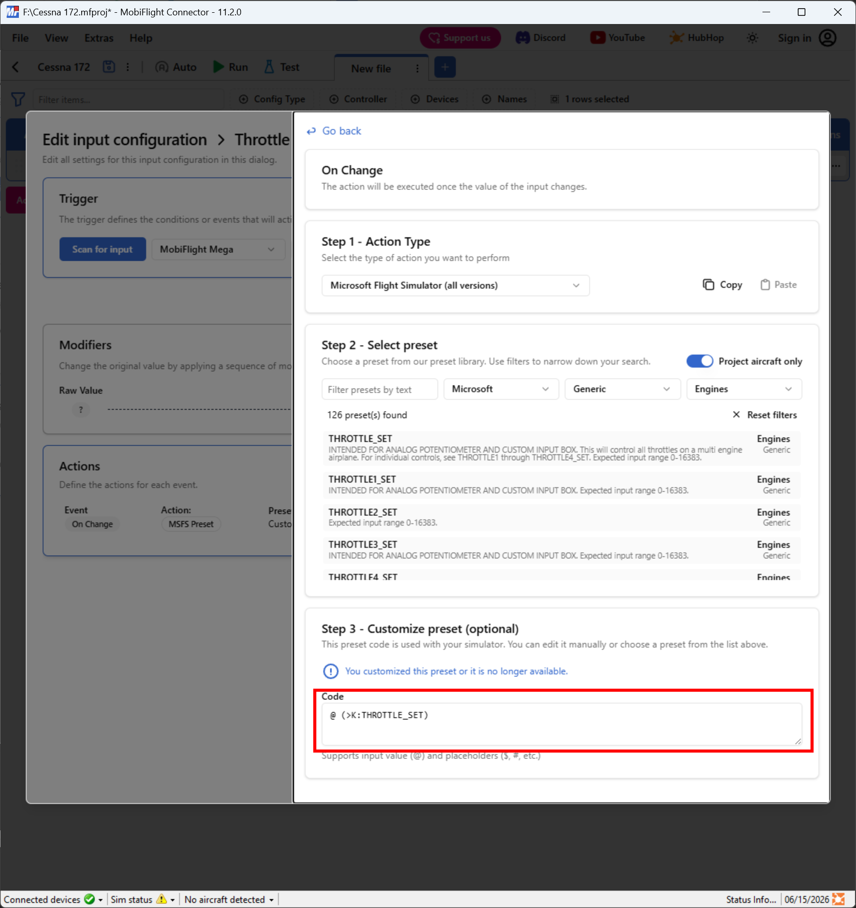
Tip
You may need to scroll the On Change pane to see the customize preset code textbox.