Advanced workshop
The advanced workshop builds a panel that includes push buttons, an LCD, and a dual encoder, to scroll through COM1 and COM2 active and standby frequencies, and to change the MHz and KHz components of the standby frequencies.
Required components
The following components are required for the project:
| Part | Quantity |
|---|---|
| Mega 2560 Pro Mini | 1 |
| MobiFlight prototyping board | 1 |
| Enclosure | 1 |
| LED push button | 2 |
| Dual encoder with breakout board | 1 |
| Micro-switch PCB | 1 |
| JST XH 3-pin wire | 1 |
| JST XH 4-pin wire | 3 |
| M3x5mm screw | 12 |
3D-printed enclosure parts
The files for 3D printing the enclosure are available in the MobiFlight workshops GitHub repo.
The workshop-advanced.3mf file contains all the parts laid out on a build plate for easy printing. Individual .stl files are also available for printing each part separately.
Assembling the boards
To assemble the prototyping board and Mega 2560 Pro Mini, connect the Mega to the back of the prototyping board. Then, connect one end of the USB cable to the Mega and the other end of the cable to your computer.
Installing the firmware and board configuration
Install MobiFlight
Use the getting started guide to install MobiFlight.
Upload the firmware
Follow the flashing ambiguous boards guide to upload the correct firmware to the Mega 2560 Pro Mini.
Upload the board configuration
Use the installing configuration guide to upload the standard configuration for a prototype board to the Mega.
Assembling the micro-switches
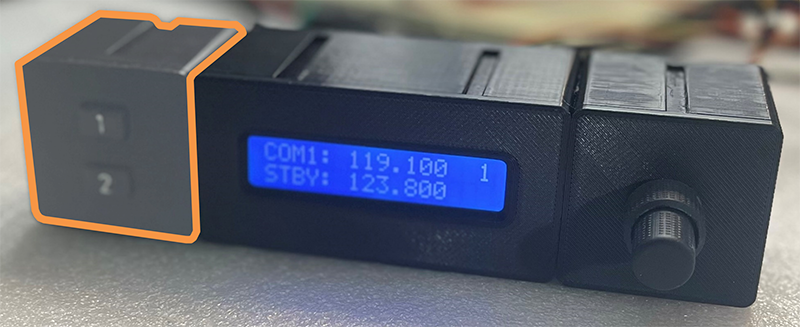
Insert the micro-switches into the lid and attach the PCB from behind with M3 screws. Plug in the JST XH 3-pin cable, and pass it through the back of the case.
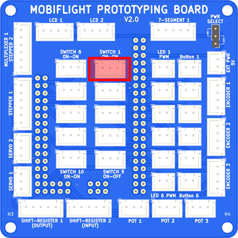
The micro-switches are connected using JST XH 3-pin cables. Connect the top switch to SWITCH 1 (ON-ON) on the breakout board.
Assembling and connecting the LCD
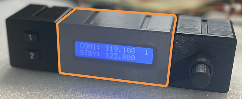
Assemble the LCD into the case lid with M3 screws. Connect the JST XH 4-pin cable to the back of the LCD, making sure to connect the black wire to GND, then pass the wire through the back of the case.
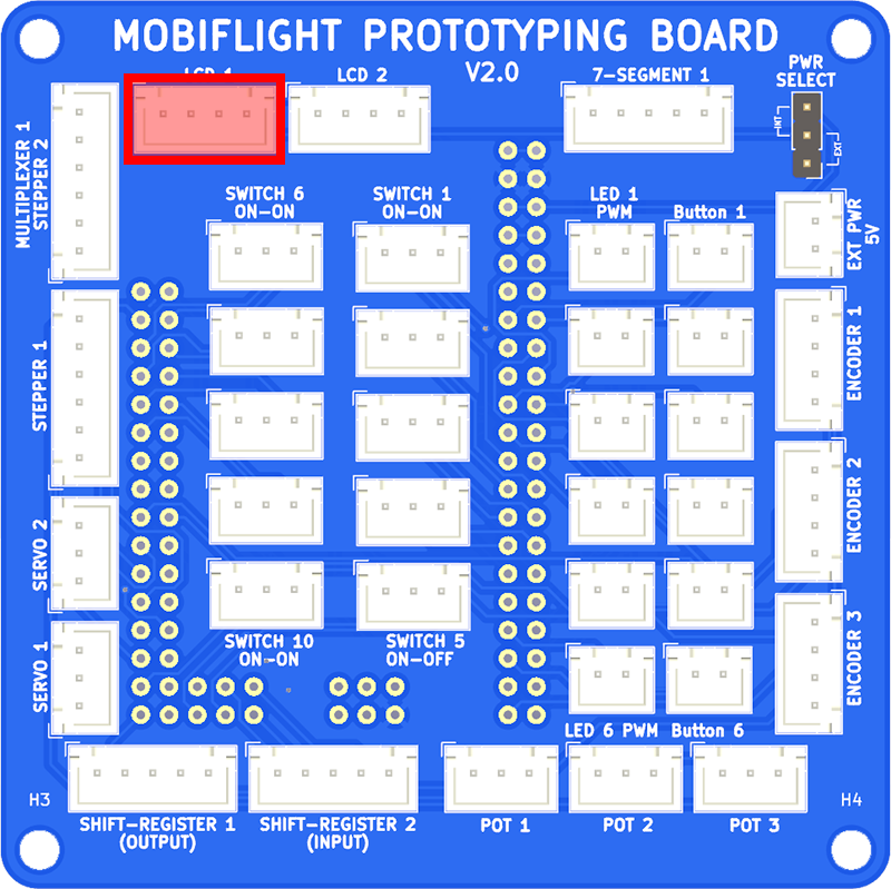
The LCD is connected using a JST XH 4-pin cable. Connect the display to LCD 1 on the breakout board.
Assembling and connecting the dual encoder
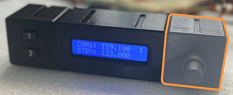
Assemble the encoder into the case using M3 screws to attach the PCB to the back of the lid. Pass the cable through the hole in the back of the case, then close the lid. Bending the cable 90 degrees, close to the PCB, helps make everything fit.
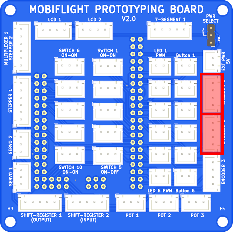
The encoder is connected using two JST XH 4-pin cables. Connect the encoder PCB INNER SHAFT connector to ENCODER 1, and the OUTER SHAFT connector to ENCODER 2, on the breakout board.
Configuring MobiFlight
The inputs and outputs are configured in MobiFlight by following the guides for each device type:
| Device description | Device name | Guide | Preset category | Preset name |
|---|---|---|---|---|
| Dual encoder - outer knob | ENCODER 1 |
Configuring encoders | Microsoft / Generic / Radio | COM_RADIO_WHOLE_DEC and COM_RADIO_WHOLE_INC |
| Dual encoder - inner knob | ENCODER 2 |
Configuring encoders | Microsoft / Generic / Radio | COM_RADIO_FRACT_DEC and COM_RADIO_FRACT_INC |
| Dual encoder - button | ENCODER 2 PUSH |
Configuring buttons | Microsoft / Generic / Radio | COM_STBY_RADIO_SWAP |
| LCD | LCD 1 |
Showing multiple pages on an LCD | See guide | See guide |
| Micro-switch - up | Switch 1-1 |
Showing multiple pages on an LCD | See guide | See guide |
| Micro-switch - down | Switch 1-3 |
Showing multiple pages on an LCD | See guide | See guide |
Next steps
With the project assembled, run Microsoft Flight Simulator, spawn in an aircraft like the Cessna 172, ensure the Run button is active in the MobiFlight toolbar, and try everything out.
Learn more about using MobiFlight in the getting started guide, discover additional supported devices, and join the MobiFlight Discord to share your project with other enthusiasts.