Settings reference
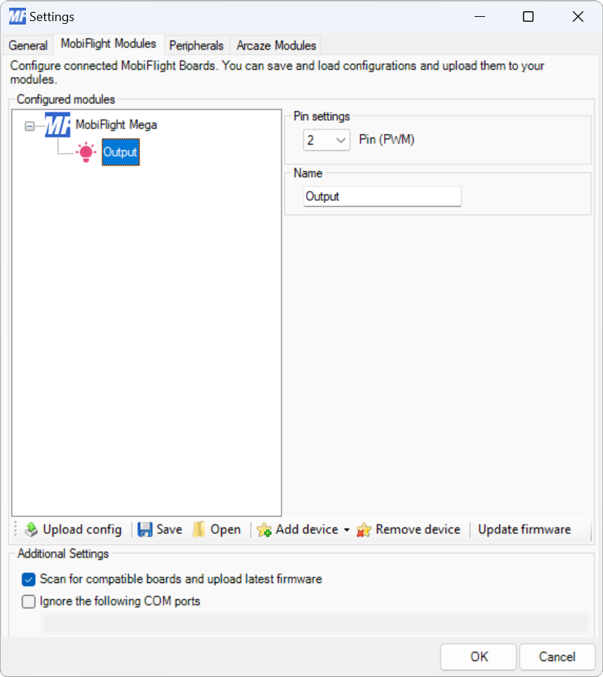
Modules dialog
| Setting | Description |
|---|---|
| Pin | The board pin connected to the LED. All digital and analog pins are supported. |
| Name | The name for the LED. Displayed in the output configuration dialog to identify the LED when mapping the simulator output to the LED. |
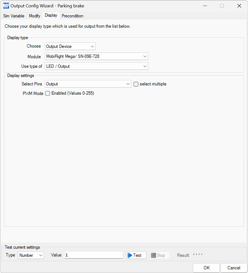
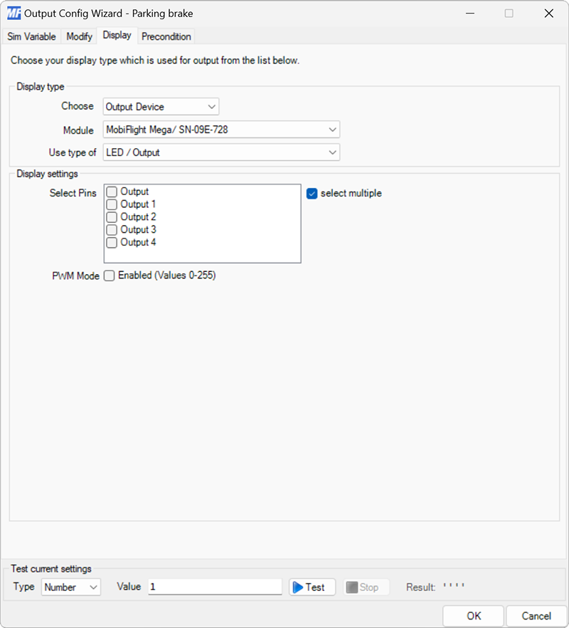
Output display configuration
| Setting | Description |
|---|---|
| Select Pins | The LED device configured in the Modules dialog to display the value on. |
| Select multiple | When checked, enables selecting multiple LED devices to display the value. |
| PWM Mode | When checked, sends values between 0–255 to the output pin instead of 0 or 1. When the LED is connected to a PWM capable pin on the board this dims the LED based on the value. |